
Toy Take-Apart
- Julian
- Mar 16, 2019
- 4 min read

The toy take-apart activity was one in which we got to find and choose whichever toy we wanted as our subject to work on. I chose a Lite-Brite as I remember playing with one as a child and wondered what made them work.

Externally, the toy itself did not have much going on. There was the pegboard on the front, a single button on the front to power on and cycle through the modes, and what appeared to be notches on the sides and back so that the toy could hang.

After some disassembly, the toy split into the casing, the three-piece pegboard, and the electronics. I was very surprised to see that there was only four LEDs used to illuminate the toy. I had it in my mind that there would be many. I supposed that this was due to the white card stock back used to disperse the lighting thought the toy.

I greatly appreciated the wire organization for the LEDs. They work as one entire circuit with a selected arrangement of colors. Colors only appeared twice as to show the direction of the current as it passed from the batteries to the LEDs and the circuit board.

Here is a closeup of the bottom of the circuit board. The microchip was located on the opposite side and started the circuit with the red and black wires located on the left while the arrangement on the right was likely meant to cut down on excessive wire.

The LEDs were housed in small plastic brackets. I removed them from these so that I could get direct access to the LEDs individually.

I developed an idea to make the toy light up similarly to a rainbow. This came from one of the settings which lit the LEDs in a circular pattern. I thought that having different colored lights would give more experimentation when using the pegs as the location of the peg would illuminate the pegs differently based on the combination of colors.

Here are the four LEDs I chose to add into my toy. I chose red, yellow, green, and blue as they cover the majority of the rainbow utilizing the wiring already in place. I was also hoping that the colliding of colors could make a sort of rainbow like effect as well.

The first LED I started with was the bottom left. I chose this one because it was the first in the cycle that I was focusing on for the rainbow animation. I tore off the original LED and used the available tools in the classroom to reveal more surface area of the wire. I wrapped the prongs of the LED around the prongs of the wire. I originally tried to use electrical tape to hold the wires together but I had trouble getting it to stay, so I settled on using the simple clear tape. It held up much better.

As you can see from this photo, the circuit stayed connected as well as a comparison of the new LED to the old ones.

The second LED I chose to work on was the top left as it was the second in the cycle I was focusing on. I used the same process for this LED as I did the last and continued it for the rest.
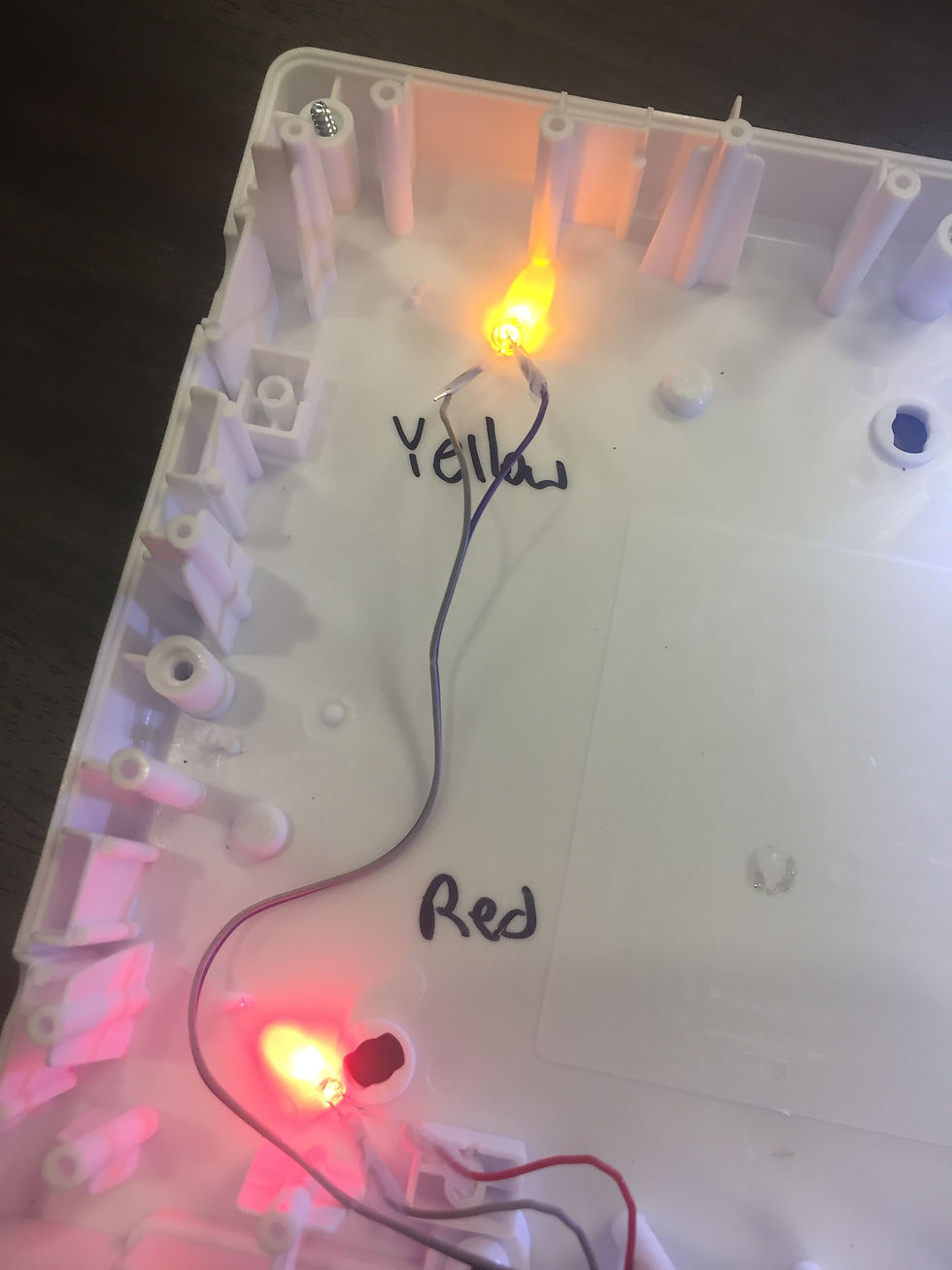
Here is a shot of the first two LEDs together in their respected places. I really liked how they were coming out.

The third LED I worked on was the top right. This was the third light in the sequence that I was focusing on to create the rainbow cycle.

Here's a shot of the almost complete toy. By this time I had gotten into the groove of how to effectively manage the wires and prongs of the LEDs.

The final light I worked on was the bottom left as it was the last in the sequence. Here you can see through the tape at the work I did in winding the wires and prongs together. I did sometimes have trouble getting the tape tights enough but in the end it all worked out through redoing it.

After replacing all of the LEDs, I replaced the white background so that the light would disperse evenly. I taped them down so that the circuits would definitely not close, however, I did not experiment enough with this and so the green LED is pointed directly at the red which mutes it. Looking back, this is something I would spend more time on.
Here is a quick video cycling through all of the modes. I left the inner silicone piece of the pegboard out so that the lights would be more visible. It is here that I saw that the green LED was distracting from the red. It also may have helped to scoot the LEDs closer to the edge of the frame for a more even disbursement of light. I do feel as though I accomplished my rainbow pattern that I set as a goal for myself.


Comments